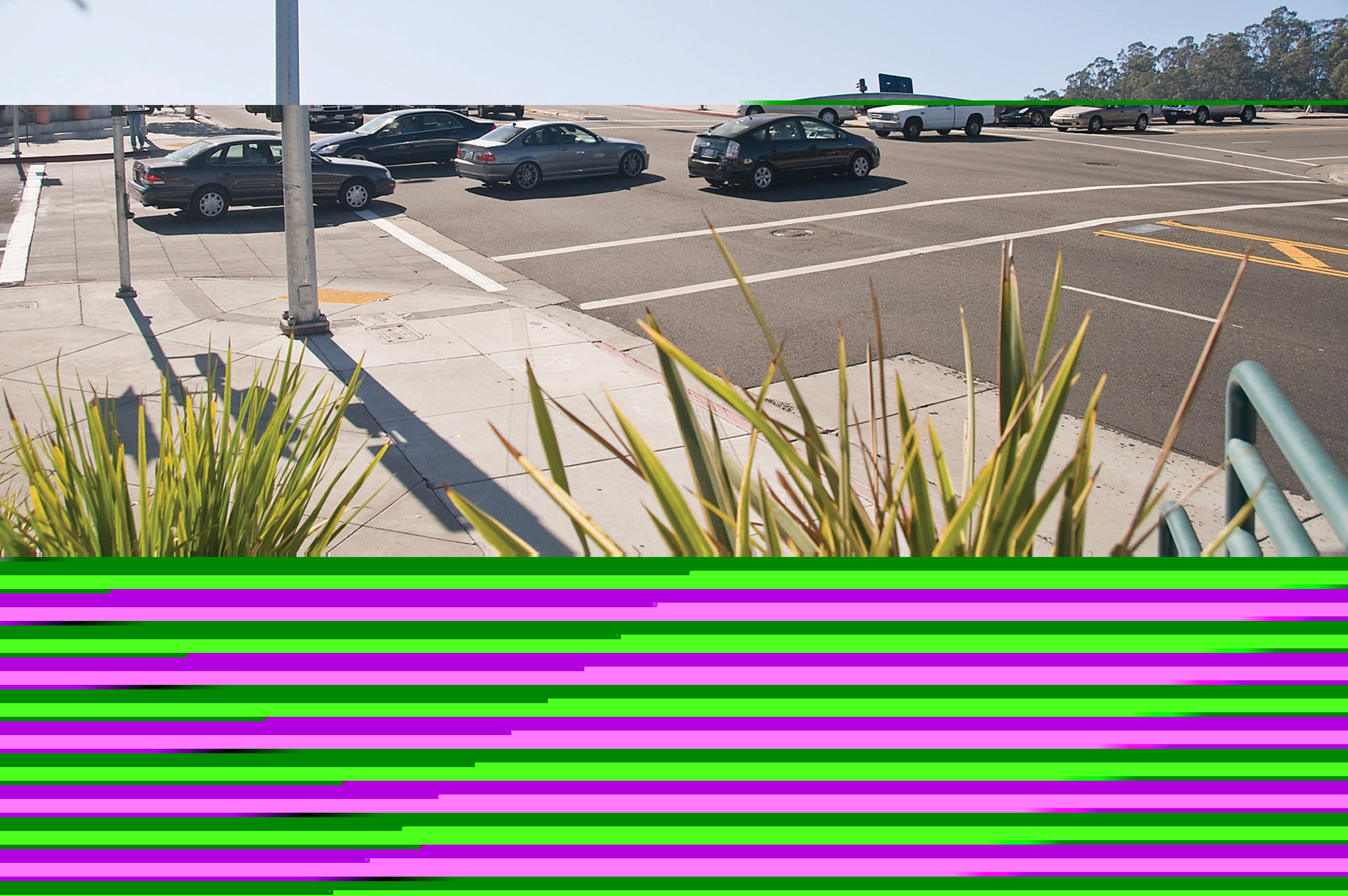
Mike Schagrin, ITS Joint Program Office, RITA, and John Harding, NHTSA, describe US progress towards an in-vehicle Intersection Violation Warning system
In 2008, there were 37,261 fatalities on US roadways. Of these, 7,772, some 20.8 per cent of the total, were defined as intersection crashes or intersection-related crashes. Through a multi-agency research initiative led by theThe IVWS prototype warns drivers when they are about to enter an intersection in violation of a traffic signal or Stop sign. Software in the vehicle analyses data from onboard sensors and that transmitted from infrastructure equipment to determine whether a driver is at imminent risk of failing to stop for a red light or Stop sign. The risk determination is based on algorithms that consider current vehicle operating conditions, the intersection geometry, GPS differential corrections and, for signalised intersections, the status of the traffic signal phasing.
Pilot field tests performance
The IVWS prototype performed well in a pilot Field Operational Test (FOT) conducted in 2007-2008 with 87 drivers who navigated a scripted, fixed route on public roads. The route included 13 instrumented intersections (three signalised and 10 Stop sign-controlled). The pilot FOT was complemented by post-test driver surveys, and by follow-up system performance testing with a subset of the drivers on a research test road. In general, the surveys indicated that drivers reacted favourably to the system.Auto manufacturer participation
The prototype development research was funded by USDOT and performed by a consortium that includedThe research was conducted under USDOT's former Cooperative Intersection Collision Avoidance System (CICAS) research programme, which was incorporated into the broader IntelliDriveSM research programme last year. Researchers call the system 'CICAS-V' (an acronym for 'CICAS Limited to Stop Sign and Traffic Signal Violations').
Development of the warning algorithm
One of the greatest challenges for researchers was to develop a system that would reliably warn drivers when appropriate, without inadvertently annoying drivers that intend to comply with traffic control devices. The system uses sensor data as inputs to a threat assessment algorithm which predicts whether the driver will comply with the intersection Stop sign or traffic signal. The algorithm must correctly predict the driver's stopping decision at a distance that provides sufficient time for that driver to stop before entering crossing traffic.The researchers based the algorithms on studies of driver and vehicle behaviour at intersections in southwest Virginia. Data collection equipment at the intersections included: radar to provide parametric vehicle data; video cameras to document the visual scene; weather stations (at signalised intersections only); a signal phase 'sniffer' to provide the signal phase and timing at signalised intersections; and a Global Positioning System (GPS).
Based on the field data collection, the researchers developed and tested 160 individual algorithms with more than 7,000 unique parameter combinations to predict whether a vehicle would violate intersection traffic control devices. Tests determined that driver/vehicle behaviour at Stop-controlled intersections differs sufficiently from signalised intersections to require the system to incorporate two separate algorithms (one for Stop-controlled intersections and one for signalised intersections).
The IVWS initiates functioning when a vehicle first enters an instrumented intersection. The vehicle's onboard sensors measure the kinematic state (position, trajectory, speed, velocity and acceleration) of the vehicle every 50 milliseconds. The kinematic measures are fed into the first layer of the algorithm, which evaluates whether the warning should be provided based on the present kinematic state of the vehicle. If it appears that the driver is in compliance, the algorithm computations cease and the system rests. If instead a violation is predicted, the present vehicle kinematics data are passed to the second layer of the algorithm. This layer evaluates the present state of the vehicle to predict whether the driver is attentive to the intersection. If the driver has started braking or is below a set speed, the warning is suppressed and the system rests. Otherwise, the warning is activated.
Development of the Driver-Vehicle Interface
Another challenge for system developers was designing the Driver-Vehicle Interface (DVI), the device that transmits the warning to the driver. The challenge is to provide effective warning that captures the driver's attention without unnecessarily distracting the driver.The researchers tested potential DVIs on VTTI's Smart Road, using drivers recruited for the purpose. The experimental vehicle was instrumented with: multiple VDI modalities, which included: a 'top of dashboard' visual warning (flashing red signal and Stop sign icon); loudspeakers to produce various types of auditory warnings; and modifications to the braking system to allow for the generation of a single brake pulse (or vehicle jerk) and Panic Brake Assist (PBA).
Results of the DVI tests concluded that a combination of brake pulse, speech warning and visual warning worked best, and that all should be included as part of the DVI warning system in the prototype.
Pilot FOT
The goal of the Pilot FOT was to stress test the system with ordinary drivers and to obtain feedback about the effectiveness and user acceptance of the warning system. Results from the Pilot FOT were used to refine the warning algorithm for Stop-controlled intersections, and the adjusted algorithm performed very well. Surveys also indicated that drivers liked the system.Objective tests
In addition to the Pilot FOT, objective tests were conducted on the VTTI Smart Road to determine whether the system performed according the to specifications defined in the systems engineering process, and to determine the FOT-readiness of system improvements that had been made based on pilot FOT results. The test procedures replicated typical scenarios that could be encountered while approaching an intersection. Procedures included approaches at different speeds, lane-change manoeuvres during the approach, driving at the edge of the lane, multiple intersections within communication range, and dynamic signal change scenarios.The tests were conducted with: test drivers who were unaffiliated with the project; an observer who recorded the test conditions and results; and a government witness. The system passed all the driving scenario tests, met or exceeded all of the engineering specifications, and was declared FOT-ready.
If considered warranted, a larger-scale FOT of the CICAS-V systems may be considered as part of the IntelliDrive research programme in the future or may be included in other testing activities planned under the USDOT's ITS Strategic Research Plan 2010 - 2014.
Other IntelliDrive intersection safety applications
Other intersection safety applications initiated under the CICAS programme and being further developed through IntelliDrive research includes Stop Sign Assist, Signalised Left Turn Assist, and Traffic Signal Adaptation. Each of these technologies uses different combinations of technologies to present information to the driver in real time. Of the four, the IVWS (CICAS-V) is the most advanced in development terms. The VTTI's Smart Road
The
The Smart Road features weather-making capabilities (rain, snow and fog), a variable lighting testbed, pavement markings, an on-site data acquisition system, road weather information systems, differential GPS, road access and surveillance, and a signalised intersection.
Dispatchers monitor the Smart Road from a computer-equipped control centre that is staffed 24/7. Researchers can observe highway traffic and driver performance, both directly and indirectly using surveillance cameras.
The fully instrumented, signalised intersection is useful for a variety of projects and tests. The intersection is reconfigurable (for example, turning lanes and crosswalks can be added as needed) and consists of two high-speed and two low-speed approaches. The intersection is equipped with customised controllers and vehicle presence sensors, as well as wireless communications.
Researchers have the ability, from the control centre, to reproduce a wide range of weather and lighting conditions on an actual highway built to state and federal highway specifications. A portion of the Smart Road is equipped with 75 weather-making towers. Each tower can rotate 360o and tilt up and down to handle changing wind conditions. Researchers can create everything from a fine drizzle to a raging downpour and, with the correct ambient conditions, snow, from a light dusting of powder to up to 4in/10cm per hour. A layer of ice can be created on the pavement to study the best systems for de-icing and anti-icing.
The Smart Road can reproduce approximately 95 per cent of all lighting situations a driver may encounter on US roads. Researchers have conducted studies on new pavement markings, new road signs, pedestrian safety and new vehicle headlamps to help drivers see more clearly in a variety of lighting and weather conditions.
In all, the Smart Road's initial two-mile test track comprises 14 experimental pavement systems. A total of 400 electronic sensors buried in the road monitor moisture penetration, the weight and speed of vehicles, and the stress and strain on the pavement.
Communications systems include a wireless LAN interfaced with a fibre-optic backbone. The network interfaces with several on-site data acquisition systems and road feature controls and may be used to transfer data between the vehicle, research building, and infrastructure within the road.


